
Cable Cross-Section vs Diameter: What Each Size Means
In a power-cable quotation, 25 mm² describes the nominal size of an individual conductor. It does not mean that the cable, or the metal conductor inside it, is 25 mm in diameter. Cable cross-section is expressed in square millimetres; diameter is a length expressed in millimetres.
Keep three descriptions separate when comparing datasheets: nominal conductor cross-sectional area, conductor diameter and overall cable diameter. The first identifies the conductor size being specified. The other two describe physical dimensions needed to understand the construction and fit the cable into an installation.
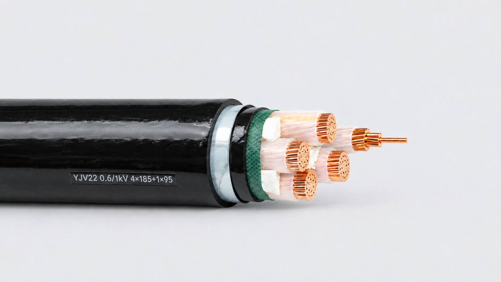
Cable cross-section and diameter: three separate terms
| Term | Unit | What it describes |
|---|---|---|
| Nominal conductor cross-sectional area | mm² | The specified conductor size, assessed with the applicable construction and electrical requirements |
| Conductor diameter | mm | The diameter of the metal conductor, excluding insulation; for a round stranded conductor, the outside of the conductor bundle |
| Overall cable diameter | mm | The outside dimension of the finished round cable, including its insulation and any other layers |
For an equal-size four-core cable, 4 × 25 mm² describes four conductors, each with a nominal cross-sectional area of 25 mm². It does not describe one 100 mm² conductor or give the finished cable diameter. Designs with reduced-size conductors need their own size description.
Check which diameter a datasheet means. An individual strand diameter, an assembled conductor diameter and a finished cable diameter are different values, even though all three can be written in millimetres.
Why nominal area is not a caliper reading
IEC 60228:2023 specifies nominal conductor cross-sectional areas together with requirements for wire numbers, wire sizes and resistance. Its applicability to a cable depends on that cable’s product standard. A size marking therefore needs to be read with the relevant conductor and cable requirements.
LAPP’s T11 conductor reference, citing IEC 60228:2004, describes nominal cross-sectional area as a conductor-size identifier rather than a quantity subject to direct measurement. This is different from measuring the geometric area of a particular piece of metal.
This distinction does not permit a supplier to ignore the specified size or acceptance requirements. The conductor still has to meet the applicable construction and electrical criteria. Resistance is an important check, but passing one resistance measurement does not replace every other requirement in the product specification.
Where the circle formula helps
For an ideal solid, round metal conductor, geometric area can be calculated as A = πd² / 4, where A is in mm² and d is the metal diameter in mm. A geometric area of 10 mm² corresponds to a diameter of approximately 3.57 mm.
That calculation excludes insulation. It is not a conversion from nominal cable size to finished cable diameter, and it does not establish whether a supplied cable complies with a standard.
For a bundle of round wires, the metal area is the sum of the individual wire areas. Drawing a circle around the whole bundle includes spaces between the wires. Compacted or sector-shaped conductors also require the appropriate geometry rather than an assumption that the entire conductor is a solid circle.
A manufacturer’s datasheet shows why the labels matter. In CADIVI’s CXV 0.6/1 kV table, the 10 mm² conductor entry has an approximate conductor diameter of 3.75 mm. The corresponding single-core cable has an approximate overall diameter of 7.5 mm. These are values for that stated copper/XLPE/PVC construction, not universal dimensions or Farwalk product specifications.
Why the same cable cross-section can have different outer diameters
Conductor construction affects how the metal occupies space. Stranding, compaction and conductor shape can change the assembled dimensions. Eland Cables explains how sector-shaped conductors can pack a multicore cable more closely than circular conductors. That does not establish a fixed diameter reduction for every cable.
Core count changes the assembly too. A single-core cable and a four-core cable can use the same nominal conductor size while having very different overall dimensions. Fillers and the arrangement of the insulated cores also occupy space.
The layers surrounding the conductors add to the finished dimensions. Insulation thickness, bedding, screens, armour and the outer sheath depend on the specified cable design. Two offers stating the same mm² size may be offering different constructions. Our XLPE and PVC insulation comparison explains the distinction between insulation and outer-sheath materials.
Before treating a diameter difference as a quality difference, compare the complete constructions. A thicker sheath does not demonstrate a larger conductor area, and a smaller overall diameter alone does not prove an undersized conductor.
Use the right dimension for the purchasing task
Specify the nominal area of each conductor together with its material, conductor class, core arrangement, voltage rating and product standard. Ask for the proposed construction and its dimensioned datasheet, especially when replacing an existing cable or working within a restricted route.
Cable glands require a physical fit. CMP’s cable gland selection guidance calls for the overall cable diameter and, for armoured constructions, additional information such as bedding diameter and armour details. A conductor size in mm² cannot supply those dimensions.
Check whether quoted diameters are approximate, nominal or subject to stated minimum and maximum values. If an accessory or entry has a limited acceptance range, obtain the relevant cable dimensions and compare them with the accessory manufacturer’s requirements. Route planning also needs the finished cable dimensions and the cable’s applicable bending limits.
For an inquiry, give the required conductor size and any physical restrictions as separate inputs. Farwalk Cable’s power cable RFQ checklist covers the remaining information needed to define a comparable offer.
What to check if the cable looks undersized
Start with the cable marking, order specification and datasheet. Confirm the declared conductor material, nominal area and construction before comparing samples. Then identify exactly what has been measured: the finished cable, the bare conductor bundle or an individual wire.
Where conductor conformity is in question, request the relevant construction checks and conductor-resistance results, including the test length and temperature basis. The resistance requirement must match the specified conductor and its applicable reference conditions; a raw meter reading without that information is not enough.
Do not accept extra insulation thickness as proof that the required conductor has been supplied. Equally, do not use an overall-diameter measurement as the sole reason to reject it. Record the observation and assess the supplied construction and test evidence against the agreed specification.
Recent Posts
October 31, 2026
Cable Storage and Handling: From Receipt to Installation
October 30, 2026
Copper vs Aluminium Cable Conductors: What Changes in an Order
Inquiry
Request a Cable Quote
Tell us the cable type, standard, voltage, conductor size, quantity and application. Our team will review your requirement.